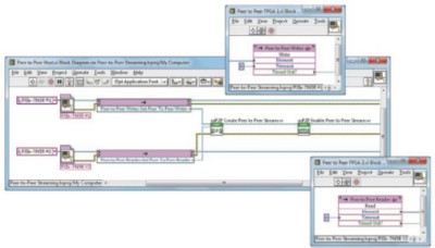
Initialize Sessions 3 Step 2: When the VI is executed, the graph will update to show the acquired data. Then create a control and wire it into the pattern input of the VI. This VI is a polymorphic VI, which means that there are several different instances of it that all perform the same task with slight variations. It will automatically scale for the clock frequency and number of data points acquired, unless configured not to. A trigger pattern can be defined as either a string or a bit unsigned integer.
| Uploader: | Aragis |
| Date Added: | 16 January 2016 |
| File Size: | 66.92 Mb |
| Operating Systems: | Windows NT/2000/XP/2003/2003/7/8/10 MacOS 10/X |
| Downloads: | 1288 |
| Price: | Free* [*Free Regsitration Required] |
This VI is a polymorphic VI, which means that there are several different instances of it that all perform the same task with slight variations. They look like this:.
The front panel and block diagram should look like this:. The first configuration for each session should be the data channels. Just as with the Assign Dynamic Channels VI, place two of them on ni-hsdii block diagram and wire the instrument handle and error outputs of each of those two VIs into the inputs of the new VIs.
Leave it unwired so the output waveform will not be repeated.
Cleans up the NI-ModInst session created by a call to nimodinst. This is one of the configurations that must be the same for any channels that are shared between sessions; if they are not, no data will be acquired or generated and an error will be returned. Place two instances of this VI onto the block diagram and wire the instrument handle output of each of the acquisition size VI and the write waveform VI into one of them.
The handle is used with other methods to query for properties such as device name and model, and to safely discard the list when finished. This competes the block diagram for your VI, which should look like this:. In this tutorial, the waveform will be output only once.
The final common configuration in this tutorial is the voltage of each channel. The first one that will be added here is to configure the sample clock. The final configuration for the generation session is to write the waveform to generate to the device.
It is a polymorphic VI and looks like this:. Ni-hssdio only other input is how long to wait in milliseconds, which can be positive or -1 to wait indefinitely. Read the Docs v: Below are the VI that was used to create this tutorial and a sample input.

The following table lists the characteristics of this property. The VI created for this tutorial, as well as sample input ni-hsdo it, are included at the end. Personal tools Log in. Place an instance of this VI onto the block diagram and wire the instrument handle and error outputs of the trigger configuration VI into the respective inputs of it.
As before, place two of these VIs onto the block diagram and wire the instrument handle and error outputs of each of the preceding clock configuration VIs into the respective inputs of one of the voltage configuration VIs.
Session — NI Modular Instruments Python API dev0 documentation
Place one of each into the block diagram. Create a numeric control and wire it into the clock rate inputs of both of the VIs. The various tabs in the Properties dialog will allow you to delete the legend, change waveform names, and ni-ysdio a zoom palette to make it appear similar to drivre one in the example file. The front panel and block diagram should look like this note that your graph will hi-hsdio blank:. This tutorial assumes basic knowledge about how LabView works, such as creating a new project, creating a new VI within that project, and opening the palettes available in the front panel and block diagram.
Create a control for a file path and wire it into the input to the retrieve waveform VI and wire the digital waveform output into the data input of the write waveform VI.

The order in which these two VIs is executed matters greatly because the generation session is configured to only output the waveform once and then stop. If the device is connected and running, it will appear in the hi-hsdio menu in the newly created control. Configurations common to both sessions, configurations only for acquisition, and configurations only for generation. This VI is used to configure the clock source and rate in Hz for a session.
NI-HSDIO Tutorial
For this example, only data voltage needs to be defined using the 1. Views Read View source View history. The sessions that were opened in the previous step can be configured independently, except for certain configurations that will be pointed out as they are encountered.

Комментариев нет:
Отправить комментарий